What this guide will help you do
Choosing the wrong PoE standard or under‑sized power budget is one of the fastest ways to create unstable IP cameras, flapping Wi‑Fi, and randomly rebooting VoIP phones. This guide explains PoE power limits in a structured, technical yet simple way so that security integrators, network engineers, and electrical contractors can size PoE correctly on the first try.
You will learn how the IEEE PoE standards map to real‑world devices, how much power actually reaches the device after cable loss, and how to calculate a safe PoE budget for a switch or injector. The focus is on three common device families: IP cameras, wireless access points (APs), and IP/VoIP phones.
PoE standards and power types
IEEE PoE generations
Power over Ethernet is defined by a family of IEEE 802.3 standards that specify voltage, maximum power per port, and how many wire pairs carry power.
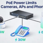
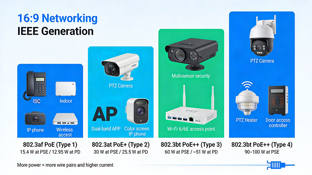
- 802.3af (PoE, Type 1)
- 802.3at (PoE+, Type 2)
- 802.3bt Type 3 (often called PoE++ or 4‑pair PoE)
- 802.3bt Type 4 (high‑power PoE)
All standards use a nominal 48–57 V DC supply, with higher power types usually operating at the higher end of the range to reduce current and data cable loss.
PoE classes vs. standards
Each PoE device advertises a class that tells the PSE how much power it might draw. The class is related to, but not the same as, the 802.3 version.
Class 0 is treated as “unknown,” so PSEs must reserve the full worst‑case power (up to 15.4 W) even if the actual draw is much lower.
Real power at the device and cable limits
Cable loss and distance
The standard 100 m Ethernet limit applies to PoE just as it does to data, but the usable PoE distance shrinks as power draw increases and cable quality drops.
- Cat5e and Cat6 both support PoE, but higher gauge (thicker copper) and better shielding reduce voltage drop.
- A low‑power IP phone drawing 5–7 W may work reliably close to 100 m, while a 15 W 4K camera on the same link may start experiencing dropouts beyond 50–60 m.
- Long runs can be extended with PoE extenders, mid‑span injectors, or by placing PoE switches closer to the devices.
When designing, always check the device datasheet for minimum input voltage and derate distance for higher‑power devices like PTZs or multi‑radio APs.
Typical PoE needs: cameras, APs, phones
IP cameras
IP cameras have some of the widest power ranges.
- Basic fixed indoor camera: 3–7 W (often 802.3af, Class 2–3).
- Outdoor bullet / dome with IR: 7–12 W, often on PoE+ to leave headroom.
- Advanced AI / multi‑sensor camera: 12–20+ W, commonly PoE+ or 802.3bt Type 3.
- PTZ with heater/blower: 25–45+ W, frequently requiring 802.3bt Type 3 or 4.
If a camera spec says “802.3af or 802.3at,” design as if it needs PoE+ so that IR, zoom, analytics, and heater can all operate at once without brown‑outs.
Wireless access points
Modern APs are usually medium‑power but can spike higher under load.
- Older 2.4 GHz or basic dual‑band APs: often 6–10 W (802.3af).
- Wi‑Fi 5/6 enterprise APs with multiple spatial streams: 13–20 W (802.3at).
- High‑density Wi‑Fi 6E / tri‑radio APs: can require 25–30+ W and may be enabled for 802.3bt Type 3.
Under‑powering an AP typically results in disabled radios or features, not a total failure, but it wastes your spectrum and client capacity.
VoIP / IP phones
VoIP phones are usually the easiest PoE load to plan.
- Basic voice‑only phone: 3–5 W, usually 802.3af.
- Phones with color screens and sidecars: 6–12 W, still within 802.3af but sometimes classified higher.
- Video phones and “collaboration endpoints”: may require 12–20 W and benefit from PoE+.
Phones are sensitive to brown‑outs because frequent reboots drop calls and registration, so keep a safety margin when doing PoE budgeting.
How to calculate a PoE power budget
Step 1: Collect device specs
List every PoE device with its maximum power consumption, not just average or typical. Use the vendor datasheet, and if the datasheet only lists a class, assume the maximum for that class.
Step 2: Sum the load
Add the maximum wattage for all devices that will connect to a given switch or injector.
Example:
- 10 dome cameras @ 12 W max = 120 W
- 4 APs @ 18 W max = 72 W
- 20 IP phones @ 7 W max = 140 W
Total = 332 W PoE requirement.
Step 3: Compare with the PoE budget
Switches often advertise both per‑port limit and total PoE budget.
- A 24‑port PoE+ switch might support 30 W per port but only 370 W total.
- You must satisfy both: no single device may exceed its port’s limit, and the sum of all active PDs must stay below the total budget.
In the example above, 332 W is below a 370 W budget, but you still need to check that high‑draw devices (like PTZs) are on ports that support PoE+ or 802.3bt.
Step 4: Add safety margin and growth
Good practice is to keep total planned usage at 70–80% of the switch PoE budget to allow for future devices, firmware changes, and inrush current. In higher‑risk environments (cold PTZs with heaters, outdoor enclosures), aim for even more headroom or dedicate injectors to those devices.
Practical design tips and comparisons
- PoE vs PoE+ vs PoE++
- Use PoE (802.3af) for low‑energy devices: basic phones, simple indoor cameras, simple sensors.
- Use PoE+ (802.3at) for anything with moving parts, IR, or multi‑radio wireless, such as PTZs and enterprise APs.
- Use 802.3bt for high‑power devices: large PTZs, multi‑sensor cameras, PoE lighting, or when aggregating several functions in one device.
- When to upsize beyond spec
- Label and document
Always document which PoE standard each port and device uses so field technicians know what can be moved where without breaking the power plan.
Common Failure Modes & Troubleshooting
- Intermittent Reboots: Classic symptom of under-powering. The device boots (low draw), activates features (high draw), hits its limit, and reboots. Solution: Upgrade to higher PoE standard.
- Switch Port Shutdown: Switch detects a fault (short, over-current) and disables port. Caused by damaged cables, non-standard PDs, or moisture.
- Poor Performance on Long Runs: At 90+ meters, voltage drop can cause a device to receive insufficient voltage (<37V), leading to brownout conditions. Solution: Use higher gauge cable (Cat6a), 4-pair powering, or a midspan injector placed closer to the device.
- PoE Negotiation Failure (Device Doesn’t Power): Ensure the PD and PSE support a common standard. Some “passive” 24V PoE devices are not IEEE-compliant and will not work with standard switches without an adapter.
Designing for Resilience and Future Growth
PoE design is an exercise in power engineering, not just network topology. The key takeaways are:
- Design to the “Guaranteed at PD” number, not the switch’s headline port power.
- Cable is a component: Specify Cat6a as a minimum for new installations where PoE is critical.
- Aggregate Power Budget is as important as per-port limits. Over-subscribe cautiously.
- Future-Proof with Higher Standards: Deploying an 802.3bt-capable switch today protects against tomorrow’s higher-wattage devices, even if you only use af/at currently.
By applying these principles, you move from simply connecting devices to engineering a robust, reliable, and scalable power delivery network—the true hallmark of a professional installation.