
Fiber selection is one of those decisions that looks simple until you’re troubleshooting a link that drops at 100 metres or trying to justify why a 10 km single-mode run needs a different transceiver than a 500 m campus backbone. The distance limits published in IEEE 802.3 and TIA standards are hard numbers tied to attenuation budgets, modal bandwidth, and transceiver power. Getting them right before you pull cable saves you from expensive re-pulls and fiber re-terminations later.
This guide walks through every mainstream fiber type, its verified distance limits per application, and the practical factors that cut those limits in real installations. Numbers here come from IEEE 802.3 (the Ethernet PHY standard), ISO/IEC 11801, and ANSI/TIA-568.2-D where applicable.
The Two Families: Multimode vs. Single-Mode
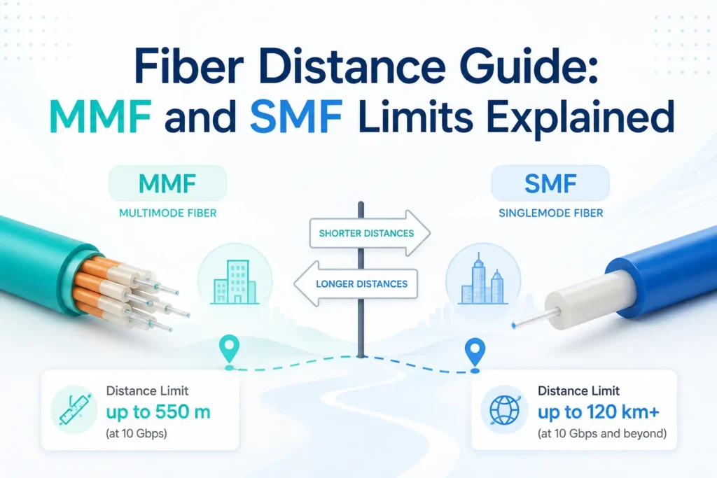
Multimode fiber (MMF) has a larger core, typically 50 µm or 62.5 µm, and uses relatively inexpensive 850 nm and 1300 nm sources. Light travels in multiple modes simultaneously, which causes modal dispersion and limits how far a signal can travel before it degrades. Single-mode fiber (SMF) has a 9 µm core, forces light into a single propagation path, and eliminates modal dispersion entirely. SMF reaches tens of kilometres but requires laser sources with tighter tolerances and higher cost.
For the vast majority of intra-building and campus work, you choose from the OM1 through OM5 multimode grades or OS1/OS2 single-mode. The OM and OS designations come from ISO/IEC 11801 and are cross-referenced in TIA-568.2-D. Each grade has a defined minimum modal bandwidth or attenuation coefficient that directly sets its distance capability at a given data rate.
Multimode Fiber Types and Their Distance Limits
OM1 and OM2: Legacy Grades
OM1 is 62.5/125 µm with a minimum overfilled launch (OFL) bandwidth of 200 MHz·km at 850 nm and 500 MHz·km at 1300 nm. OM2 is 50/125 µm with 500 MHz·km at 850 nm. Both predate the laser-optimized era. You still find them in buildings wired in the 1990s and early 2000s.
At 1 Gbps (1000BASE-SX), OM1 reaches 275 m and OM2 reaches 550 m. At 10 Gbps (10GBASE-SR), OM1 is limited to 33 m and OM2 to 82 m. Those are not typos. If you have an existing OM1 or OM2 plant and you’re moving to 10G, the fiber is the bottleneck, not the switches. Replacing it with OM3 or OM4 is almost always the right call rather than trying to engineer around it.
OM3: The 10G Workhorse
OM3 is laser-optimized 50/125 µm with a minimum effective modal bandwidth (EMB) of 2000 MHz·km at 850 nm. It was designed specifically for 850 nm VCSELs used in SFP+ and QSFP transceivers. This is the minimum grade TIA-568.2-D recommends for new installations supporting 10G or higher.
At 10GBASE-SR, OM3 runs 300 m. At 40GBASE-SR4 (parallel optics over MPO), it reaches 100 m. At 100GBASE-SR10 or 100GBASE-SR4, you get 100 m. For 1G applications, OM3 covers 1000 m at 850 nm. These are the channel distances including connectors, splices, and patch cords.
OM4: Extended Reach for High Density
OM4 is also laser-optimized 50/125 µm but with a higher minimum EMB of 4700 MHz·km at 850 nm. That extra bandwidth extends the 10G reach to 550 m and pushes 40G and 100G parallel optic links to 150 m. If you’re designing a campus backbone or a large data centre where some runs will push 400 to 500 m, OM4 is the right choice over OM3 without going to single-mode cost.
OM4 is backward compatible with OM3 transceivers. You can use OM4 cable with OM3-rated SFP+ modules, but your distance is governed by the transceiver specification, not the cable. Always confirm transceiver compatibility with the actual module datasheet.
Need Network Cabling in Toronto?
Free onsite survey within 48 hours. TIA-568 certified, Fluke DSX tested every run.
OM5: Wideband Multimode
OM5 (WBMMF, wideband multimode fiber) is 50/125 µm with a minimum EMB of 4700 MHz·km at 850 nm (matching OM4) plus an additional specified bandwidth at 953 nm. It was designed to support short-wave division multiplexing (SWDM) technology, which uses multiple wavelengths across the 850 to 953 nm window to carry multiple data streams over a single fiber pair, allowing 40G or 100G over duplex LC instead of MPO parallel optics.
With SWDM4 transceivers, OM5 supports 100GBASE-SW over 150 m on a duplex pair. For standard 10GBASE-SR applications without SWDM, OM5 behaves identically to OM4 and delivers the same 550 m. OM5 is lime green in colour per TIA-568.2-D to distinguish it from OM3 (aqua) and OM4 (violet or aqua with violet labelling). The premium over OM4 is modest enough that specifying OM5 for new builds is reasonable if SWDM is on your roadmap.
Single-Mode Fiber: OS1 and OS2
Single-mode fiber eliminates modal dispersion. Distance is governed by attenuation, chromatic dispersion, and transmitter power rather than bandwidth. The two grades are OS1 and OS2, differentiated by their maximum attenuation coefficient.
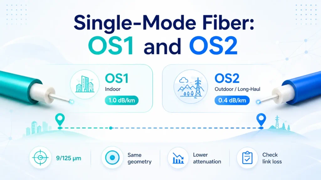
OS1 specifies a maximum of 1.0 dB/km at 1310 nm and 1550 nm. It is typically tight-buffered or used in indoor-rated loose tube constructions. OS2 specifies a maximum of 0.4 dB/km at 1310 nm and 0.4 dB/km at 1550 nm, and is the dominant choice for outside plant and long-haul runs where attenuation budget matters.
For Ethernet applications, 1000BASE-LX covers 5 km on OS1/OS2 with standard transceivers and up to 10 km with long-reach variants. 10GBASE-LR reaches 10 km on OS2. 10GBASE-ER extends to 40 km with erbium-doped fibre amplifiers or appropriate launch power. 100GBASE-LR4 covers 10 km, 100GBASE-ER4 covers 40 km. For dark fibre WAN and carrier interconnects, DWDM systems regularly operate over hundreds of kilometres with optical amplification, though those are outside the scope of a standard structured cabling design.
OS1 and OS2 use the same 9/125 µm geometry and are physically interchangeable. The difference is the cable construction and attenuation specification, not the fiber glass itself. Mixing OS1 and OS2 in a single link is acceptable as long as your total attenuation budget still meets the transceiver’s loss tolerance. Calculate the actual link loss. Do not assume.
Distance Limits at a Glance
| Fiber Type | 1GBASE-SX/LX | 10GBASE-SR/LR | 40G (SR4/LR4) | 100G (SR4/LR4) |
|---|---|---|---|---|
| OM1 (62.5 µm) | 275 m (SX) | 33 m (SR) | Not supported | Not supported |
| OM2 (50 µm) | 550 m (SX) | 82 m (SR) | Not supported | Not supported |
| OM3 (50 µm) | 1000 m (SX) | 300 m (SR) | 100 m (SR4) | 100 m (SR4) |
| OM4 (50 µm) | 1000 m (SX) | 550 m (SR) | 150 m (SR4) | 150 m (SR4) |
| OM5 (50 µm) | 1000 m (SX) | 550 m (SR) | 150 m (SR4) / 440 m (SWDM) | 150 m (SR4) / 150 m (SWDM4) |
| OS1 SMF (9 µm) | 5 km (LX) | 2 km (LR, link budget limited) | 10 km (LR4) | 10 km (LR4) |
| OS2 SMF (9 µm) | 10 km (LX) | 10 km (LR) | 10 km (LR4) | 10 km (LR4) |
What Actually Reduces Your Distance Budget
Connector Loss
Every mated connector pair introduces attenuation. TIA-568.2-D allocates a maximum of 0.75 dB per mated pair for multimode field-terminated connectors. Pre-polished connectors (splice-on or mechanical) and factory-terminated assemblies typically run 0.1 to 0.3 dB per pair when clean. In a channel with four connectors (patch panel in, patch panel out, equipment cord at each end), you can easily consume 0.6 to 1.0 dB just in connectors before you account for cable attenuation. Keep connections clean. Use lint-free wipes and isopropyl alcohol rated for fiber before every mating, every time.
Splice Loss
Fusion splices, done well on single-mode fiber, run 0.02 to 0.1 dB each. Mechanical splices run higher, typically 0.2 to 0.5 dB. On a long outside plant run with multiple splices, this adds up. Your OTDR trace will show each splice event. Budget 0.3 dB per splice conservatively when planning; verify actual loss after installation.
Bend Radius Violations
Multimode fiber has a minimum bend radius of 10 times the cable diameter during installation and 1 times during rest for standard fiber, though cable manufacturer specs vary. Exceeding bend limits causes microbend and macrobend losses that don’t always show as a discrete OTDR event but raise the overall attenuation floor. Single-mode fiber is more sensitive to bending. Bend-insensitive single-mode fiber (ITU-T G.657) is worth specifying for inside plant runs with tight conduit routing.
Planning a cabling project in the GTA?
Velocity Cabling designs and installs structured cabling, fiber, and security systems for businesses across Toronto, Mississauga, Brampton, and the surrounding area.