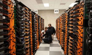

A 90 W PoE++ port loses part of its power as heat inside the cable. One cable on its own sheds that heat easily. Put 48 of them in a tight bundle and the cables in the middle can run 8 to 18°C hotter than the air around them, depending on the cable and the pathway. That extra heat pushes the cable toward its temperature rating, and it raises insertion loss, which shortens the distance the link can reliably carry data.
This guide is for IT managers, consulting engineers and installers planning high-power PoE in offices, warehouses and telecom rooms. It works from the published numbers in TIA TSB-184-A, the TIA length derating table and the Canadian Electrical Code, so you can size bundles and runs before the cable goes in, not after a PTZ camera starts dropping off the network.
Key takeaways
- TIA TSB-184-A limits the temperature rise inside a powered bundle to 15°C. That figure assumes a maximum ambient of 45°C and cable rated for 60°C.
- With every cable carrying 90 W Type 4 current in an open pathway, the 15°C limit holds up to 52 Cat5e, 74 Cat6 or 100 Cat6A cables per bundle. In conduit those numbers fall to 24, 52 and 64.
- Hot cable carries data a shorter distance. Unscreened cable at an average 50°C supports about 79.5 m of horizontal cable, not 90 m.
- Shorter runs do not cool a bundle. Heat per metre depends on what the device draws, not on how long the cable is.
- Under CEC Rule 16-330, equipment rated 60 W or less on 24 AWG or larger conductors is exempt from bundle limits. 90 W Type 4 devices and thinner cables are not.
Why PoE Heats the Cable
Copper has resistance. Push DC current through it and some of the energy turns into heat. Power over Ethernet sends that current down the same pairs that carry your data, so every powered cable is also a very long, very thin heating element.
IEEE 802.3 builds this loss into each PoE type. The power sourcing equipment (PSE), usually your switch, has to put out more than the powered device (PD) is guaranteed to receive. The difference is the worst-case loss over a 100 m channel, and all of it ends up as heat in the cable and connectors.
| PoE type | Standard | Switch port output | Guaranteed at device | Worst-case cable loss | Current per pair |
|---|---|---|---|---|---|
| Type 1 (PoE) | 802.3af, 2 pairs | 15.4 W | 12.95 W | 2.45 W | 350 mA |
| Type 2 (PoE+) | 802.3at, 2 pairs | 30 W | 25.5 W | 4.5 W | 600 mA |
| Type 3 (PoE++) | 802.3bt, 4 pairs | 60 W | 51 W | 9 W | 600 mA |
| Type 4 (PoE++) | 802.3bt, 4 pairs | 90 W | 71.3 W | 18.7 W | 960 mA |
The loss column is the allowance for a worst-case channel. A good Cat6 or Cat6A link loses less than that. Still, the trend matters more than the exact watts, because resistive heat rises with the square of the current. Fluke Networks puts it simply: 50% more current produces 125% more heat.
We ran the numbers on a single cable using the IEEE maximum currents. On the same piece of Cat6, a Type 4 port running flat out produces about 5 times the heat of a PoE+ port and about 15 times the heat of original 802.3af PoE. Type 4 doubles the energized conductors from four to eight and raises the current on each one. Both changes add heat.
A single cable in open air gets rid of that heat without trouble. A bundle is different. The cables in the centre are surrounded by other warm cables, so heat builds until the bundle settles at a steady temperature above the surrounding air. That difference is called temperature rise, and it is what the standards limit.
If you are still working out how much power each device needs, start with our guide to planning PoE power for cameras, access points and phones, then come back here to plan the cabling side.
The 15°C Rule From TIA TSB-184-A
TIA TSB-184-A, Guidelines for Supporting Power Delivery Over Balanced Twisted-Pair Cabling, is the North American reference for PoE cabling. ISO/IEC TS 29125 covers the same ground internationally. Both are guidelines rather than code, but they are what manufacturers, consultants and warranty programs design to.
The core rule is short: the temperature rise at the centre of a bundle should not exceed 15°C. The logic comes from simple arithmetic.
Cable temperature rating ≥ ambient temperature + bundle temperature rise
Most premises cable is rated for 60°C. TIA assumes the hottest ambient a cable will see is 45°C. That leaves 15°C of headroom for heat from PoE.
Four things decide how much of that 15°C a bundle uses:
- Bundle size. More cables means more heat sources and a longer path for heat to escape from the centre.
- Current and energized pairs. Type 3 and Type 4 power all four pairs. Type 4 also runs the highest current.
- Conductor gauge and construction. Thicker copper has lower resistance. Category 6A cable, with larger conductors and a larger overall diameter, runs cooler.
- Pathway. A bundle hanging in open air on J-hooks loses heat by convection. The same bundle inside conduit or a closed raceway does not.
For new installations aimed at 4-pair PoE, both TSB-184-A and ISO/IEC TS 29125 point to Category 6A, because it allows larger bundles for a given current and ambient temperature.
How Many 90 W PoE++ Cables Can Share a Bundle?
The chart below plots the TSB-184-A temperature rise data for Type 4 PoE, with every cable in the bundle carrying current. Solid lines are bundles in open air. Dashed lines are bundles in conduit.
A few data points show how quickly the numbers move:
- A 24-cable bundle of Cat6 rises about 6°C in open air and about 8.7°C in conduit.
- Double it to 48 cables and Cat6 rises about 10°C in air and about 14°C in conduit.
- At 100 cables in open air, Cat6A rises about 14.8°C, Cat6 about 17.6°C and Cat5e about 22.6°C. Only Cat6A stays inside the limit.
Conduit costs you a lot. For bundles between 19 and 100 cables, the same bundle runs roughly 30 to 45% hotter in conduit than in open air.
Maximum bundle size for your heat budget
The 15°C budget only holds if the ceiling never goes above 45°C. If the space runs hotter, your budget shrinks degree for degree. We took the TSB-184-A Type 4 data and worked out the largest tabulated bundle that stays within three budgets, assuming standard 60°C-rated cable.
| Heat budget | Hottest ambient | Cat5e air | Cat5e conduit | Cat6 air | Cat6 conduit | Cat6A air | Cat6A conduit |
|---|---|---|---|---|---|---|---|
| 15°C | 45°C | 52 | 24 | 74 | 52 | 100 | 64 |
| 10°C | 50°C | 24 | 19 | 48 | 24 | 52 | 37 |
| 5°C | 55°C | 7 | 1 | 7 | 7 | 19 | 7 |
How to read it: if your ceiling can reach 50°C, a bundle of Cat6 cables all running 90 W should not exceed 48 cables on J-hooks or 24 in conduit. The values are the largest bundle sizes TSB-184-A lists without going over the budget, so the true limit sits somewhere between that row and the next one up.
Two cautions. First, the table assumes typical 23 and 24 AWG constructions. Thin cables run much hotter. Superior Essex, for example, allows 74 of its 23 AWG Cat6A cables per bundle for Type 4, but only 24 of its 26 AWG Cat6A. Second, every cable in the table is drawing full Type 4 current. A bundle where half the cables feed 6 W desk phones will run cooler. More on that below.
Hot Ceilings Shorten the Link
Heat also changes how the cable carries data. Insertion loss, the signal lost along the cable, goes up as copper gets warmer. The 90 m horizontal and 100 m channel limits assume the cable is at 20°C.
Need Network Cabling in Toronto?
Free onsite survey within 48 hours. Fluke DSX tested to TIA-568 limits.
TIA-568 adjusts insertion loss for unscreened (UTP) horizontal cable by 0.4% per °C between 20°C and 40°C, and 0.6% per °C between 40°C and 60°C. Screened cable is adjusted by only 0.2% per °C across the whole range. To keep the channel within its loss limit, the standard reduces the allowed horizontal cable length as temperature rises.
| Average cable temperature | Max horizontal, UTP | Max horizontal, screened |
|---|---|---|
| 20°C | 90.0 m | 90.0 m |
| 30°C | 87.0 m | 88.5 m |
| 40°C | 84.0 m | 87.0 m |
| 50°C | 79.5 m | 85.5 m |
| 60°C | 75.0 m | 83.0 m |
Two practical points. First, you cannot fix this on the tester. Fluke Networks notes that adjusting the insertion loss pass line for temperature is not permitted under TIA, ISO/IEC or IEEE rules. The fix is a shorter link, designed in from the start. Second, screened cable holds its length far better in heat. Fluke puts the derating for Cat6A UTP at 60°C at about 18 m, against about 7 m for Cat6A F/UTP. The exact figure depends on the cable’s own temperature coefficient, so check the manufacturer’s data sheet.
This sits on top of the distance limits you may already know, such as why Cat6 only supports 10 Gbps up to 55 metres. For the physics behind both effects, see the physics of attenuation and crosstalk.
Where hot ceilings show up in the GTA
A conditioned office ceiling rarely gets near 45°C. The risk sits in other spaces: warehouse and distribution centre ceilings under a steel roof deck, mezzanines, older industrial units without ceiling insulation, mechanical rooms, and pathways that run past unit heaters or rooftop equipment. ISO/IEC TS 29125, the international PoE cabling guideline, recognises that an ambient of 50°C is possible in some environments.
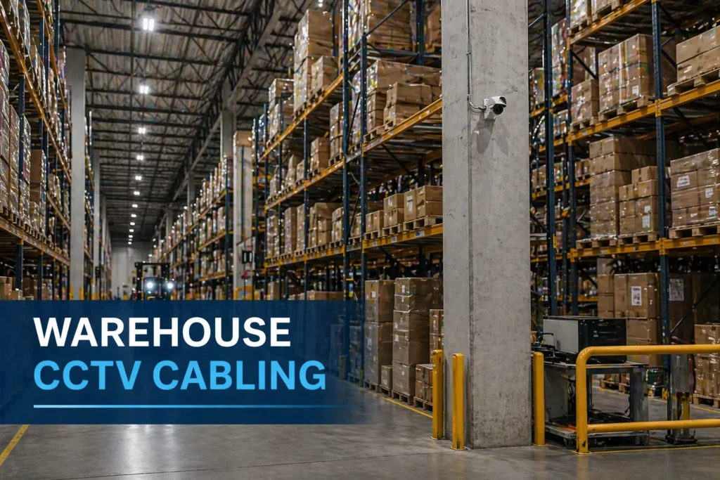
Do not guess. Before sizing bundles for a warehouse or industrial space, put a temperature logger at cable-tray height for a hot week in July. A sensor costs very little compared with re-pulling a camera run. On long warehouse runs, such as the J-hook pathways feeding Wi-Fi and camera drops across a large distribution centre, the measured peak decides both your bundle size and your maximum link length.
Worked example: 48 PoE++ cables in a warehouse ceiling
A distribution centre is adding PTZ cameras and high-power access points. The plan puts 48 Cat6 UTP cables in one bundle on J-hooks across the ceiling, all feeding devices that run close to Type 4 power. A logger shows the ceiling air at 40°C on a hot afternoon.
- Find the bundle rise. TSB-184-A gives about 10°C for 48 Cat6 cables in open air.
- Find the cable temperature. 40°C ambient plus 10°C rise puts the cable at about 50°C.
- Check the rating. 50°C is below the 60°C rating, and a 10°C rise is inside the 15°C limit. On temperature alone, the design passes.
- Check the length. At 50°C, UTP supports about 79.5 m of horizontal cable. Any permanent link over about 79 m that spends most of its length in that ceiling is outside the design limit, even if it certified cleanly on a cool day in April.
- Check the conduit option. Put the same bundle in conduit and the rise climbs to about 14°C. The cable reaches about 54°C, the length limit drops to about 77.7 m, and only 6°C of margin remains before the 60°C rating.
Now the fixes. Split the bundle into two bundles of 24 and the rise falls to about 6°C, so the cable sits near 46°C and UTP links can run about 81 m. Switch to Cat6A F/UTP in bundles of 24 and the rise is about 5°C, the cable sits near 45°C, and the screened derating allows about 86.5 m. That second option costs more per metre, but it can save a second IDF in a long building.
One honest caveat: the derating table uses the average temperature along the whole run. If the first 20 m of a link sits in a cooler telecom room, its average is lower. For runs that spend most of their length in the hot zone, design to the hot number.
Why Shorter Runs Do Not Cool a Bundle
This is the point most people miss. It seems logical that a shorter cable makes less heat. In total it does, but bundle temperature depends on heat per metre, and that barely changes with length.
A PoE device draws a set amount of power. The current it pulls is fixed mainly by that load, not by how far away the switch is. Since heat per metre comes from current and the resistance of each metre of copper, a 20 m cable and a 100 m cable feeding the same device heat up almost the same amount per metre.
Data presented to the IEEE 802.3 working group shows this clearly. For a 71.3 W load on 24 AWG cable, heat per metre was about 100 mW over 100 m, 87 mW over 50 m and 80 mW over 20 m. Cutting the run by 80% cut the heat per metre by only 20%.
That has two consequences on real jobs:
- The hottest spot is often right above your racks. Every cable converges on the ladder rack or basket tray near the telecom room. Short or long, they all carry full current through that densest section. Plan bundle sizes there first.
- Count devices, not ports. A 90 W switch port feeding a 6 W desk phone adds almost no heat to the bundle. Heat follows what the devices actually draw. Plan bundles around the real peak load of the cameras, access points, displays and lighting on each run, and keep the 90 W loads spread across bundles.
Shorter runs still help with voltage drop and insertion loss. They do not solve bundle heat. Fewer cables per bundle, larger conductors, open pathways and lower real power draw do.
Code Rules: Ontario, the Rest of Canada and the US
TSB-184-A is about performance. Electrical codes are about safety, and they treat PoE bundles separately.
Canadian Electrical Code (CEC) and Ontario
The CEC added rules for PoE in its 2018 edition. Rules 16-300 to 16-350 in Section 16 cover what the code calls Class 2 power and data communication circuits. The current edition is CSA C22.1:24, the 26th edition. In Ontario it is adopted, with Ontario amendments, as the 29th edition of the Ontario Electrical Safety Code, in force since May 1, 2025.
The rules that matter for bundling:
- Rule 16-320 limits power supplies for these circuits to 100 VA and 60 V dc.
- Rule 16-330 sets the maximum current per conductor from Table 60, based on conductor size, the cable’s temperature rating and the number of cables in the bundle.
- The exemption: under Rule 16-330, communication equipment rated 60 W or less, supplied by cable with conductors of at least 24 AWG, does not have to meet the bundling requirements.
| Situation | CEC bundle limits from Table 60? |
|---|---|
| Phones, cameras and access points at 60 W or less on 23 or 24 AWG Cat5e, Cat6 or Cat6A | Exempt. TIA bundle guidance is still good practice. |
| Any 90 W Type 4 device | Yes. Above the 60 W exemption. |
| Devices at 60 W or less on 26 or 28 AWG slim cable | Yes. Conductors are smaller than 24 AWG. |
This catches people out with slim-diameter Cat6A. Its smaller cable is handy in crowded pathways, but 26 AWG conductors fall outside the exemption and run hotter in a bundle. Interpretation on a specific project rests with the electrical designer and the inspection authority, so raise high-power PoE at the design stage, not at inspection.
US National Electrical Code (NEC) and LP cable
For projects south of the border, the 2017 NEC added Section 725.144 and an ampacity table for 4-pair data cables. It sets the maximum current per conductor by gauge, temperature rating (60°C, 75°C or 90°C) and bundle size in steps from 1 cable up to 192, at a 30°C ambient. Panduit’s reading of the 2017 table, for example, allows a 23 AWG cable rated 60°C to carry 0.5 A per conductor in bundles of up to 91 cables. As Panduit notes, the table only comes into play for Type 4 PoE, above 60 W at the source.
The NEC also created an optional Limited Power (LP) cable marking, such as CL2-LP (0.5A). UL tests LP cable in a 192-cable bundle, and a cable with the LP marking can be bundled in any number, as long as the current per conductor stays at or below the marked rating. That makes inspection simple: check the LP rating instead of counting cables.
Code and performance are different targets. The NEC table works from a 30°C ambient and protects the cable from overheating. TSB-184-A plans for up to 45°C ambient and protects data performance. A bundle can meet code and still run hot enough to shorten your links.
Installation Checklist for High-Power PoE
- List the real loads. Write down each device’s actual peak draw and PoE type. Mark every run that will carry Type 3 or Type 4 power.
- Measure the pathway temperature. Log the hottest section of every pathway in summer, especially in warehouses and industrial units.
- Choose Cat6A, 23 AWG, for new high-power builds. It allows the largest bundles. Avoid 26 AWG slim cable for big horizontal bundles carrying 90 W.
- Consider screened cable in hot spaces. F/UTP loses far less length to heat. If you go screened, the bonding and grounding have to be done right end to end. Our shielded vs unshielded guide covers the trade-offs.
- Cap bundles at 24 cables. EN 50174-2 and ISO/IEC 14763-2 both limit data cable bundles to 24. Belden’s summary of TSB-184-A and CommScope’s installation guidance recommend the same cap for PoE.
- Leave air between bundles. The same standards call for a gap of 0.3 times the bundle diameter between bundles longer than 1 m. A 24-cable bundle is about 50 mm across, so leave about 15 mm.
- Prefer open pathways. J-hooks and basket tray with cables laid in flat layers shed heat better than conduit or closed raceway. Our cable tray installation work is planned with this in mind.
- Do not cinch tight round bundles. Over-tightened ties and tightly combed bundles trap heat and can affect crosstalk. Use hook-and-loop straps, snug but not tight.
- Watch patch cords. TIA-568.2-D allows 28 AWG patch cords but recommends keeping them under 15 m in a channel. CommScope recommends bundling no more than 12 of them.
- Specify connectors tested for PoE++ unmating. Unplugging a powered link can arc across the contacts. IEC 60512-99-002 covers Type 3 and Type 4 PoE, so ask for jacks and plugs tested to it. That includes the field-terminated plugs used on MPTL links to cameras and access points.
- Spread the 90 W loads. Do not group every PTZ camera on one bundle. Mix high-power runs with low-power ones.
- Document it. Record pathway temperatures, bundle sizes and derated maximum lengths in the as-built records, so the next person adding a 90 W device knows the limits.
Every copper link we install is certified on a Fluke DSX, and for high-power projects we plan the bundle layout and maximum link lengths before cable is ordered. If you are planning PoE++ for a warehouse, office or campus, see our Cat6A cabling services in Toronto or our warehouse CCTV installation work.
Frequently Asked Questions
Sources
- Lightera, PoE in Bundles of 24 to 192 Cables (reproduces TIA TSB-184-A Type 4 temperature rise data)
- Fluke Networks, Temperature impacts your insertion loss measurement and An Exception to Every Rule
- IEEE 802.3 Working Group, Practical PoE tutorial (heat per metre by cable length)
- Panduit, NEC and PoE tech brief
- IAEI Magazine, Guide to the CEC, Section 16 and What is LP cable?
- Electrical Safety Authority, Ontario Electrical Safety Code
- Telegärtner, Spacing of cable bundles when using PoE
- CommScope, Power over Ethernet FAQ
- Superior Essex, PoE FAQs, TG092
Planning high-power PoE in the GTA?
Velocity Cabling plans bundle sizes, pathways and link lengths around the devices you are actually installing, then certifies every copper link. We serve offices, warehouses and industrial sites across Toronto, Mississauga, Brampton, Vaughan and the wider GTA.